
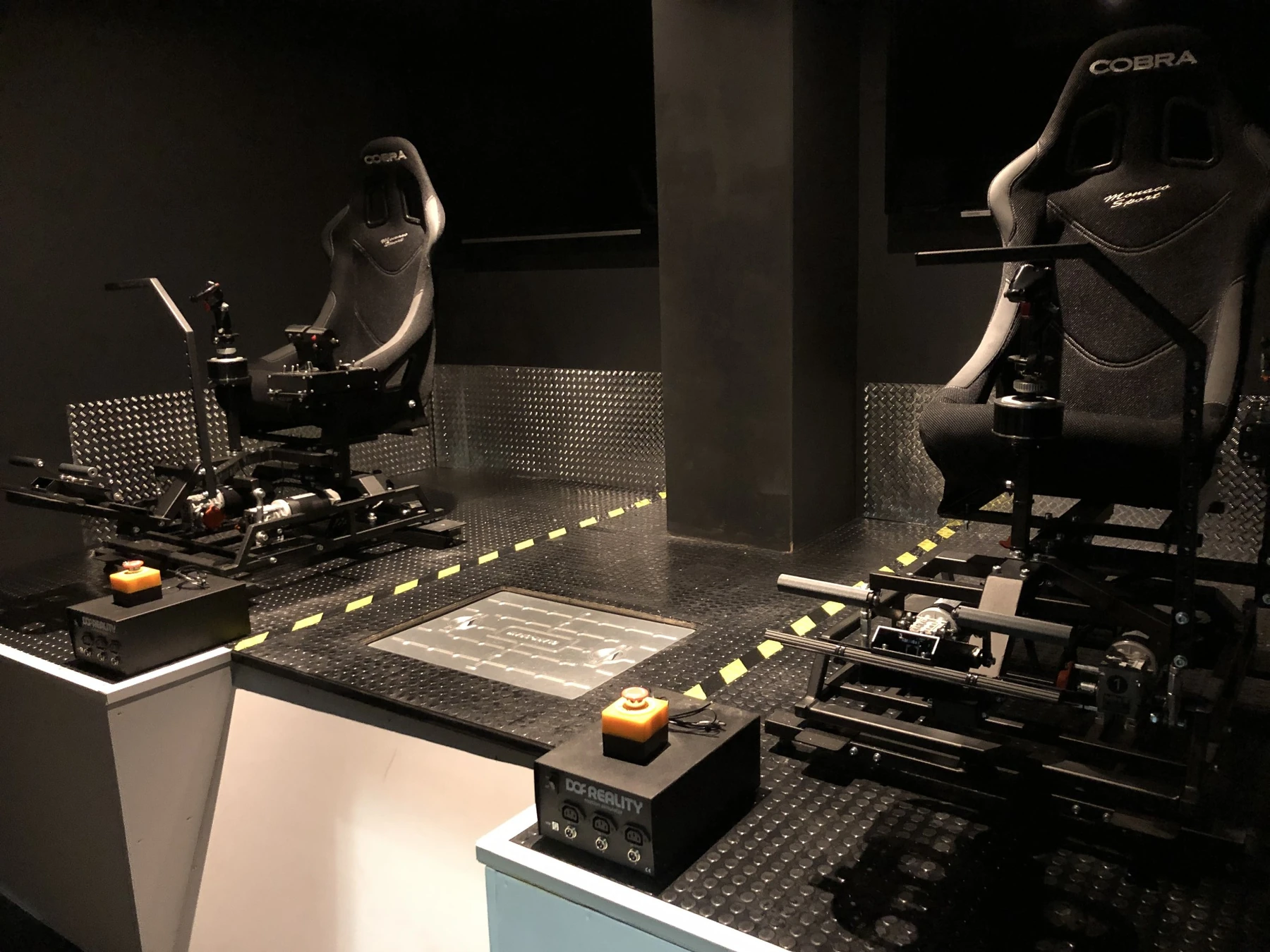
A physical platform for a virtual cockpit
Virtual reality provides the visual environment, while each station supplies the seat, flight controls, pedals and moving platform. The project brings these elements together within a compact installation rather than relying on a full enclosed fighter cockpit.
The photographs show the actual integrated hardware and its supporting structure. Some components carry their original supplier branding. This case study describes our development and integration of the installation; it does not claim that Red Cosmos manufactured every seat, control device or motion-platform component.
Motion and airflow cues
The installation uses three-axis motion alongside fan-driven airflow intended to reinforce the sensation of movement, speed and acceleration. These cues supplement the virtual scene and the participant's interaction with the controls.
Airflow is a sensory cue, not a substitute for real sustained acceleration or aircraft G-loading. We do not present a physiological performance claim, motion range or response figure without a defined specification and supporting measurement. The effect is described here as part of the project's immersive design intent.
Cooperative and separate-aircraft scenarios
The system can place both participants within the same simulated aircraft, allowing them to work together as a crew. Alternatively, they can operate separate aircraft within a shared virtual environment. The owner-described scenario range includes formation flying, air combat and dogfights.
These are different ways of using the installation, not evidence of military procurement or endorsement. The project is presented for its simulation and integration capabilities, with any proposed use or software configuration to be confirmed individually.
A shared instructor position
Rear screens show the virtual view seen by each participant. A single instructor position at the front can observe and manage a variety of scenarios. This makes supervision part of the installation layout rather than an afterthought.
For a new project, the design discussion would include the operator's view of each station, access to controls, participant communication and the point at which an experience can be paused or stopped. The photographs show emergency-stop hardware as part of this installation, without implying a separate safety certification.
Consolidating the supporting equipment
Computing equipment, wiring looms and connections are located beneath the simulators. This arrangement is intended to keep the hardware within a small overall footprint and avoid scattering the supporting equipment around the room.
A compact layout still needs to account for service access, cabling, ventilation, entry and exit, and clearance around moving parts. The platform dimensions alone do not establish a complete room requirement. Those allowances need to be reviewed against the actual configuration and site.
Hardware integration in detail
The close-ups show flight sticks, twin-throttle controls, pedal assemblies, control mounts and the motion mechanisms. The wider views show how the two stations relate to the shared platform and observation screens. We have retained distinct views and omitted duplicate uploads from the published gallery.
Together, the photographs illustrate the practical work of combining multiple interfaces into a coherent installation. The system is non-accredited. No guaranteed training outcome, combat readiness claim or official affiliation is implied by the scenarios it can represent.